Products

Coil Heaters

SPECIFICATIONS AND OPTIONS
Engineering Specifications
Standard sheath material 304 stainless steel
For temperatures up to 1500°F (815°C)
Optional sheath material Inconel® 600 up to 1800°F (980°C)
For aggressive atmospheres
Standard thermocouple ANSI Type J
Optional thermocouple ANSI Type K
Minimum bending radius Three times the sheath diameter

VINAYAK coil heaters feature continuous operating temperatures up to 1200°F (649°C). Rapid heating and cooling occur, due to the low mass construction. All heating elements are sealed from contamination and the stainless steel sheath provides maximum corrosion resistance. An optional internal thermocouple may be utilized for overtemp control.

Design Features

  • Continuous operating  temperatures to 1200°F (649°C)
  • Intermittent  operating  temperatures to 1500°F (815°C)
  • Rapid heating and cooling due to low mass construction
  • Heating elements sealed from contamination
  • Stainless steel sheath for corrosion resistance
  • Optional internal thermocouple for temperature control.

Typical Applications

  • Blow Molding
  • Custom Die Applications
  • Extrusion
  • Hot Runner Systems
  • Injection Molding
  • Thermoforming
  • Others, Consult Vinayak
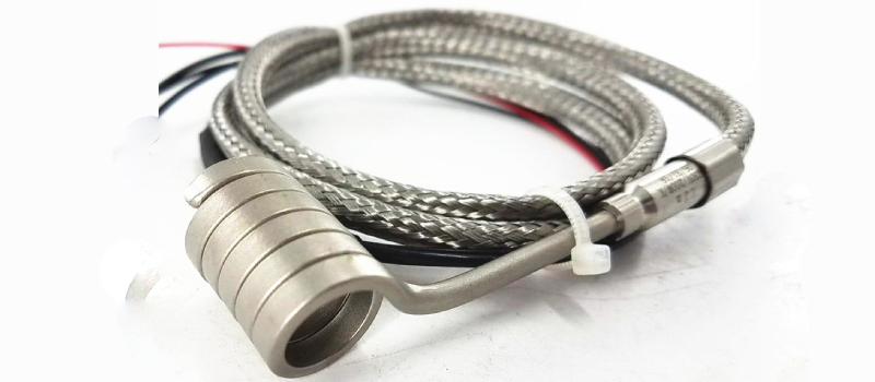
Dimensional Specifications
Standard square cable 0.125″ square
Standard rectangle cable 0.080″  x 0.140″, 0.105″ x 0.150″, 0.130″ x 0.130″, 0.100″ x 0.120″
Standard round cable  diameters 0.093″, 0.125″, 0.150″,  0.188″, 0.200″, 0.250″
Other dimensions available
Cable diameter tolerance ± 0.005
Standard potting adapter 0.25″ to 0.38″ diameter (See chart)
Standard potting adapter length 0.88″ to 1.20″ (See chart)
Other lengths available
Standard coil  I.O.: From  3/s” up to 2Vz” in any increments
Applicable coil inner diameter is subject to cable  diameter
Coil  I.D. tolerances: 3/s” to 31:!”, + 0.000″,- 0.020″
%”to 1%”, + 0.000″,- 0.030″
1Vz” to 2Vz”, + 0.000″, – 0.060″
Coil length Up to 12″ on 3/s” to%” I.D.
Up to 16″ on%” to 1%” I.D.
Up to 18″ on 1Vz” to 2Vz” I.D.
Coil length  tolerance 0 to 6″: + 0, – Vs”
6 to 12″: + Vs”,- %”
12 to 18″: ± %”
Electrical Specifications
Resistance tolerance  ± 10%
Wattage tolerance ± 10%
Maximum amperage Size dependent,consult factory
Standard Voltage 120 or 240 volts
For higher or lower voltages contact Industries
SPECIFICATIONS AND OPTIONS

Sheath Cross Section Maximum Voltage Adapter Minimum Bend Radius
Diameter Length
0.062 Dia. 120 0.25 1.16 0.18
0.093 Dia. 120 0.28 0.88 0.28
0.125 Dia. 240 0.28 0.88 0.38
0.080 X  0.140 240 0.28 0.88 0.38
0.100 X  0.120 240 0.28 0.88 0.38
0.150 Dia. 240 0.28 0.88 0.45
0.105 X  0.150 240 0.28 0.88 0.45
0.130 X  0.130 240 0.28 0.88 0.45
0.188 Dia. 240 0.38 1.20 0.56
0.200  Dia. 240 0.38 1.20 0.60
0.250 Dia. 240 0.38 1.20 0.75